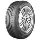
REXROTH CDH1系列液压油缸 南平市建阳区迪必达自动化科技有限公司
面议
福建-南平市
有效期长期有效

Rexroth standard
Series H1
Component series 3X
Nominal pressure 250 bar
Piston Ø 40 … 320 mm
Piston rod Ø 22 … 220 mm
Stroke length up to 6000 mm
Feature
6 types of mounting
Self-adjusting and adjustable end position cushioning
Technical data
general
Installation position
any
Priming
Gentian blue (RAL 5010), see Table Corrosivity categories
Minimum layer thickness of the priming 1)
µm
40
Painting 2)
in four corrosivity categories in the RAL colors, see Table Corrosivity categories1)Other colors upon request.
With cylinders and attachment parts, the following surfaces are not primed:
▶ All fit diameters to the customer side
▶ Sealing surfaces for line connection
▶ Sealing surfaces for flange connection
▶ Connection surface for valve mounting
▶ Inductive proximity switches
▶ Position measurement system
▶ Measuring coupling
▶ Spherical / plain bearing
▶ Lubricating nipples2)With cylinders and attachment parts, the following surfaces are not painted:
▶ All fit diameters and connection surfaces to the customer side
▶ Sealing surfaces for line connection
▶ Sealing surfaces for flange connection
▶ Connection surface for valve mounting
▶ Inductive proximity switches
▶ Position measurement system
▶ Measuring coupling
▶ Spherical / plain bearing
▶ Lubricating nipples
The areas that are not primed or painted are protected by means of a solvent-free corrosion protection agent.
Accessories that are ordered as separate order item are not primed or painted by default. Corresponding priming and/or painting on request.
hydraulic
Nominal pressure 1)
bar
250
Operating pressure, min. (without load) 2)
10
Static test pressure
375
Reduced test pressure
315
Operating viscosity range
mm²/s
12 … 380
Optimum viscosity at operating temperature
20 … 100
Maximum admissible degree of contamination of the hydraulic fluid, cleanliness class according to ISO 4406 (c) 3)
Class 20/18/15 according to ISO 4406 (c)
Bleeding
By default secured against screwing out1)The maximum operating pressures must be less than or equal to the applicable nominal pressures and apply to applications with shock-free operation with reference to excess pressure and/or external loads. With extreme loads like e. g. high sequence cycle, mounting elements and threaded piston rod connections must be designed for durability.2)Depending on the application, application conditions and technical design, a certain minimum pressure (approx.10 bar) is required in order to guarantee technically unobjectionable functioning of the hydraulic cylinder.3)The cleanliness classes specified for the components must be adhered to in hydraulic systems. Effective filtration prevents faults and simultaneously increases the life cycle of the components. For the selection of the filters, see www.boschrexroth.com/filter.
Hydraulic fluid
Classification
Suitable sealing materials
Standards
Data sheet
Mineral oil
HL, HLP
FKM,NBR
DIN 51524
90220
Oil-in-water emulsion
HFA
FKM, NBR
ISO 12922
90223
Water glycol
HFC
upon request
Phosphate ester
HFD-R
FKM
90222
Polyol ester
HFD-U
Weight
Piston
Piston rod
with 0 mm stroke length
per 100 mm stroke length
ØAL
ØMM
MP3/MP5
MF3/MF4
MT4
MS2
Weight without position measurement system
mm
kg
4022 mm / -79990.928 mm / -799915028 mm / -101412121.236 mm / -101412131.56336 mm / -162219192.145 mm / -162219202.68045 mm / -253029312.956 mm / -263130323.610056 mm / -435250524.670 mm / -445351535.712570 mm / -799391907.390 mm / -809593929.214090 mm / -11112713013110.7100 mm / -11212813113211.9160100 mm / -16819820020912.6110 mm / -16920020221013.9180110 mm / -23627026927814.7125 mm / -23927227128116.8200125 mm / -30634834635819140 mm / -30935134936121.5220140 mm / -45251547950927.1160 mm / -45251547950930.9250160 mm / -58266461864932.7180 mm / -58266461864936.9280180 mm / -75384678482244.2200 mm / -75384678482248.8320200 mm / -112512901180122255.2220 mm / -112512901180122260.4
Selection criteria for seals
Work and environmental conditions
Seal versions
M
G
V
L
A
B
T
R
S
Medium/temperature
Medium HL, HLP/operating temperature of medium ‒20 … +80 °C
++
Medium HFA/operating temperature of medium +5 … +55 °C
+/‒
+/-
+
Medium HFC/operating temperature of medium ‒20 … +60 °C
‒
Medium HFDR/operating temperature of medium ‒15 … +80 °C
Medium HFDU/operating temperature of medium ‒15 … +80 °C
Ambient and rod temperature in the area of the piston rod ‒20 … +80 °C1)
+2)
++2)
Extended ambient and rod temperature in the area of the piston rod +80 … +120 °C
Function/velocity …
Static holding function more than 10 minutes:Attention! Application- and temperature-dependent
Static holding function short-time < 1 minute
Robust application conditions: steel works, mining, thin ice
Zero point control, hardly any amplitude, frequency ≤ 5 Hz, max. 5 minutes
Cylinder velocity ≥ 0.001 m/s stick-slip behavior
Cylinder velocity 0.01 … 0.5 m/s3)
Cylinder velocity > 0.5 … ≤ 0.8 m/s3)
Stroke length > 1.0 m
Standstill period (wear)
Undissolved air in the oil4)
++ = very good
+ = good
+/– = conditional, depending on the application parameters
– = inappropriate
General technical data in corresponding data sheets will remain valid! See table on hydraulic fluids!
Generally, a medium temperature of approx. 40 °C is recommended. The specified values are to be regarded as guidelines; depending on the case of application, it may be necessary to check the suitability of the seal system.1)Moreover, observe the corresponding medium temperature range2)Lower temperature limit –15 °C3)Standard line connections not designed for that velocity4)‒ = Seal is destroyed, + = Seal is not directly destroyed, leakage may occur
Stroke velocity
Piston Ø
Line connection
Maximum stroke velocity 1)
m/s
40G1/20.31500.263G3/40.28800.18100G10.2125G 1/41400.16160G 1/20.181800.142000.112200.092500.072800.063200.041)Please observe the guideline on max. stroke velocities (with recommended flow velocity of 5 m/s in the line connection) in the table. Higher stroke velocities upon request. If the extension velocity is considerably higher than the retraction velocity of the piston rod, drag-out losses of the medium may result. If necessary, please consult us.
The mechanical alignment of the movement axis and thus the mounting points of hydraulic cylinder and piston rod must be ensured. Lateral forces on the guides of piston rod and piston are to be avoided. It may be necessary to consider the own weight of the hydraulic cylinder (MP3/MP5 or MT4) or the piston rod.
▪
The bending length/bending load of the piston rod and/or the hydraulic cylinder must be observed (see bending).
The maximum admissible stroke velocities with regard to the suitability/load of seals must be observed as must their compatibility with the properties of the hydraulic fluid (see seals).
The maximum admissible velocities/kinetic energies when moving into the end positions, also considering external loads, must be observed.Danger: Excess pressure
The maximum admissible operating pressure must be complied with in any operating state of the hydraulic cylinder. Possible pressure intensification resulting from the area ratio of annulus area to piston area and possible throttling points are to be observed.
Detrimental environmental influences, like e.g. aggressive finest particles, vapors, high temperatures, etc. as well as contaminations and deterioration of the hydraulic fluid are to be avoided.
Diameters, areas, forces, flow
Piston
Area ratio
Areas
Force at 250 bar
Flow at 0.1 m/s
Maximum available stroke length
Piston
Rod
Ring
Pressure
Differential
Traction
Off
On
ØAL
φ A1/A3
A1
A2
A3
F1
F2
F3
qV1
qV2
qV3
cm²
kN
l/min
4022 mm / -1.4312.563.88.7631.4 1)9.521.97.5 2)2.35.3200028 mm / -1.9612.566.166.431.4 1)15.4167.5 2)3.73.820005028 mm / -1.4619.636.1613.4749.1 1)15.433.711.8 2)3.78.1200036 mm / -2.0819.6310.189.4549.1 1)25.4523.6511.8 2)6.15.720006336 mm / -1.4831.1710.1820.9977.9 1)25.4552.4518.7 2)6.112.6200045 mm / -2.0431.1715.915.2777.9 1)39.7538.1518.7 2)9.59.220008045 mm / -1.4650.2615.934.36125.65 1)39.7585.930.2 2)9.520.7200056 mm / -1.9650.2624.6325.63125.65 1)61.5564.130.2 2)14.815.4200010056 mm / -1.4678.5424.6353.91196.35 1)61.55134.847.1 2)14.832.3300070 mm / -1.9678.5438.4840.06196.35 1)96.2100.1547.1 2)23.124300012570 mm / -1.46122.7238.4884.24306.75 1)96.2210.5573.6 2)23.150.5300090 mm / -2.08122.7263.6259.1306.75 1)159.05147.773.6 2)38.235.4300014090 mm / -1.7153.9463.6290.32384.75 1)159.05225.792.4 2)38.254.23000100 mm / -2.04153.9478.5475.4384.75 1)196.35188.492.4 2)47.145.33000160100 mm / -1.64201.0678.54122.5502.5 1)196.35306.15120.6 2)47.173.53000110 mm / -1.9201.0695.06106502.5 1)237.65264.85120.6 2)5763.63000180110 mm / -1.6254.4795.06159.43636.17 1)237.65398.52152.7 2)5795.73000125 mm / -1.93254.47122.72131.75636.17 1)306.8329.37152.7 2)73.679.13000200125 mm / -1.64314.16122.72191.44785.25 1)306.8478.45188.5 2)73.6114.93000140 mm / -1.96314.16153.96160.2785.25 1)384.9400.35188.5 2)92.496.13000220140 mm / -1.68380.1153.9226.2950.3 1)384.9565.5288.1 2)92.4135.76000160 mm / -2.12380.1201179.1950.3 1)502.6447.7288.1 2)120.7107.46000250160 mm / -1.69490.8201289.81227.2 1)502.6724.5294.5 2)120.7173.86000180 mm / -2.08490.8254.4236.41227.2 1)636.2591294.5 2)152.7141.86000280180 mm / -1.7615.7254.4361.31539.4 1)636.2903.2369.4 2)152.7216.76000200 mm / -2.04615.7314.1301.61539.4 1)785.4753.9369.4 2)188.5180.96000320200 mm / -1.64804.2314.1490.12010.6 1)785.41225.2482.5 2)188.52946000220 mm / -1.9804.2380.1424.22010.6 1)950.31060.3482.5 2)228.12946000
![]()
1)Theoretical static cylinder force (without consideration of the efficiency and admissible load for attachment parts such as swivel heads, plates, or valves, etc.)2)Stroke velocity

Tolerances according to DIN ISO 6022
Installation dimensions
WC
XC2)
XO2)
XS1); 2)
XV2)
ZP2)
Mounting type
MF3
MP3
MP5
MF4
Stroke length in mm
Tolerances in mm
Stroke tolerances in mm
3)
≤ 1250
±2
±1,5
+2
> 1250 – ≤ 3150
±4
±3
+5
> 3150 – ≤ 6000
±8
±5
+8
1)Not standardized2)Including stroke length3)Stroke tolerances must not be added to the tolerances listed in this table.
免责声明:当前页为 REXROTH CDH1系列液压油缸 南平市建阳区迪必达自动化科技有限公司产品信息展示页,该页所展示的 REXROTH CDH1系列液压油缸 南平市建阳区迪必达自动化科技有限公司产品信息及价格等相关信息均有企业自行发布与提供, REXROTH CDH1系列液压油缸 南平市建阳区迪必达自动化科技有限公司产品真实性、准确性、合法性由店铺所有企业完全负责。世界工厂网对此不承担任何保证责任,亦不涉及用户间因交易而产生的法律关系及法律纠纷,纠纷由会员自行协商解决。
友情提醒:世界工厂网仅作为用户寻找交易对象,就货物和服务的交易进行协商,以及获取各类与贸易相关的服务信息的渠道。为避免产生购买风险,建议您在购买相关产品前务必确认供应商资质及产品质量。过低的价格、夸张的描述、私人银行账户等都有可能是虚假信息,请您谨慎对待,谨防欺诈,对于任何付款行为请您慎重抉择。
投诉方式:fawu@gongchang.com是处理侵权投诉的专用邮箱,在您的合法权益受到侵害时,请将您真实身份信息及受到侵权的初步证据发送到该邮箱,我们会在5个工作日内给您答复,感谢您对世界工厂网的关注与支持!


电话13959199347
手机13959199347
微信13959199347
QQ1045498665
地址南平市建阳区黄花山路45号大潭印象1幢3单元901室